Abstract
Elettronica SpA designs and produces systems for electronic warfare. Each system design is unique according to its platform and purpose. In this article, the company describes how it used CAE to approach the challenging design of a single sandwich radome to protect a large terrestrial system for signal intelligence that used more than 40 ultra-wide band UWB antennae to detect threats.
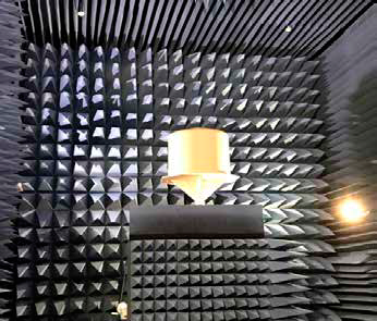
The radome was specified as roughly cylindrical shape with a diameter of 1 m and a height of 0.8 m, strong enough to withstand difficult environmental conditions while also being electromagnetically transparent from the DC band up to the 40 GHz band. During the design process, the engineers found that the model’s extensive spatial domain was too complex for their available computational resources. Th series of approximations they subsequently inserted in the simulation created simulation artifacts that distorted their initial design conclusions. The article describes how this simulation challenge was overcome.
Read the article