This paper, by means of presenting three application cases, provides a brief description of the capabilities of a numerical tool developed for the design and optimization of hybrid metal/composite lattice structures created with 3D printing. The tool allows a large number of axial symmetrical structures to be generated in the ANSYS environment through the use of a macro written in APDL language. The models generated can be used for both sensitivity analyses and structural optimization processes (they are totally parametrized). The strength of the procedure is its ability to generate many unit cells by defining a matrix structure that activates specific connectivity flags. The models generated are not too expensive computationally due both to the simplification of the models (made with beam and shell elements) and to the elimination of any possible multiple point constraints (MPC) elements between the nodes of the lattice structure and the remaining solid parts.
This enables the finite element (FE) models generated to also be used for more expensive analyses such as non-linear buckling ones.

CASE STUDY
Read the fascinating articles on the vast subject of structural engineering, beginning with a philosophical bent and arguing for the necessity of a skillful and artful intertwining of Engineering, Numerical Simulation, Art and Technology to achieve structures that are both eminently functional yet attractive and appealing.
civil-engineering
CASE STUDY
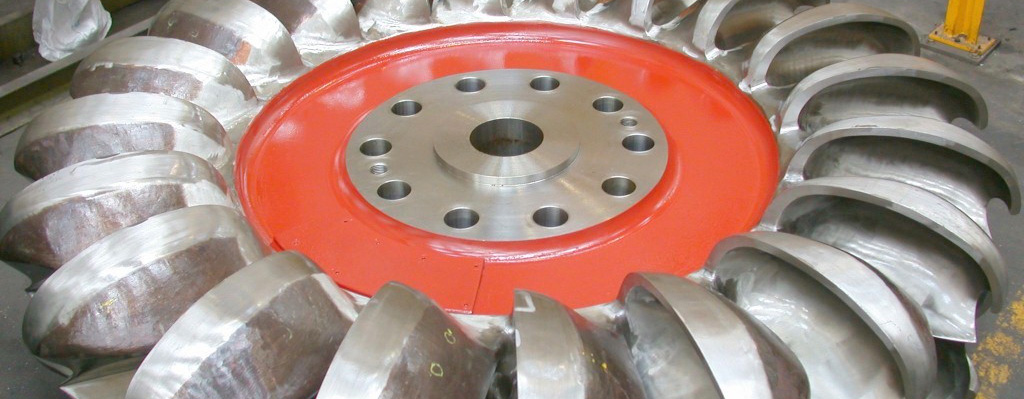
EnginSoft developed a Computational Fluid Dynamic (CFD) analysis methodology for the performance evaluation of a Pelton turbine
energy cfd ansys oil-gas