New approach for accurate, robust morphing of CAD geometries
Facilitates bi-di transfer between analysis-testmanufacture and design
Newsletter EnginSoft Year 16 n°1
By Andrew Chinn | International TechneGroup
Connecting simulation and test results into the design process, such that analysis truly leads design, offers potentially significant breakthroughs for manufacturers.
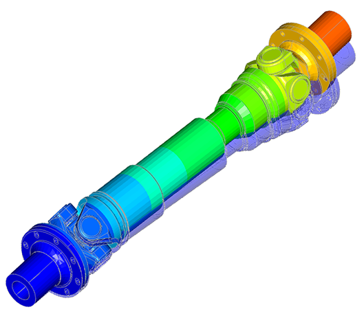
This technical article describes a new, automated approach to accurately and robustly morph CAD geometry based on results of analysis in order to facilitate the missing bi-directional transfer of these geometries between analysis/test/manufacture and design.
Two industrial examples using this approach are also provided, in the morphing of a turbine blade deformation model and aero-elastic deformation of aerodynamic shapes for the NASA Common Research Model. This technique is particularly useful for cases requiring multi-disciplinary analysis and automatic shape optimization for further, independent CAE analysis.
Read the article
CASE STUDY
Read the fascinating articles on the vast subject of structural engineering, beginning with a philosophical bent and arguing for the necessity of a skillful and artful intertwining of Engineering, Numerical Simulation, Art and Technology to achieve structures that are both eminently functional yet attractive and appealing.
civil-engineering
CASE STUDY
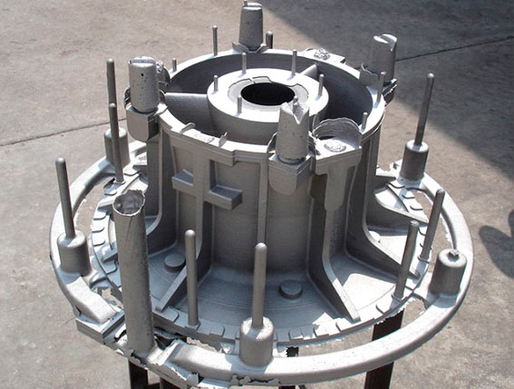
The scope of this study was to determine and validate a more efficient simulation procedure for the design phase of Al-Si alloy components for the aeronautical industry.
aerospace magma metal process simulation