Standards compliance requires expansion valve producers to supply detailed user manuals that accurately specific the
refrigerant capacity of their valves.
This article details a study that was undertaken by Castel, a producer of refrigeration
and air conditioning components, to compare the results of an experimental method for testing expansion valves with a
numerical method using Ansys.
Expansion valves for refrigeration and air conditioning applications are used to take the refrigerant fluid from its condensation pressure to its evaporation pressure. This pressure drop is achieved by a shutter and an orifice, both of which must be appropriately designed to ensure that the whole system functions correctly, in particular to maintain a constant set-point temperature in the cold room. The other important purpose of this device relates to the superheating parameter which must be regulated and kept constant for the compressor to function correctly.
Electric expansion valves (EEV) are the most reliable and efficient of all expansion valves. Technologically, they are based on a stepper motor that provides precise regulation of the valve shutter position, allowing it to respond accurately to variations in the thermal load in the cold room. They require a driver and two sensors, one to control pressure and one for temperature. (Fig. 1).
All expansion valves must be supplied with a manual, an important document that must specify their refrigerant capacity. Castel’s EEV portfolio includes several valve models that differ mainly in their geometrical dimensions and in the expressed mass flow rates, which depend on the pressure drop through the valve and on the refrigerant fluid, since each refrigerant has a unique capacity to transfer heat.
The company therefore needed a precise method to obtain the capacity values for all its EEV models in order to compile the EEV manuals so that refrigeration equipment manufacturers could select the most suitable components for their applications.
Read the article
CASE STUDY
The adoption of SBES has significantly increased in the last two decades, driven by advancements in computing technology and the rise of Industry 4.0, which promotes nine key enabling technologies, including engineering simulation and big data analytics. SBES is crucial for the integration and automation of production systems, improving flexibility, speed, and quality.
automotive construction energy cfd metal-process-simulation
CASE STUDY
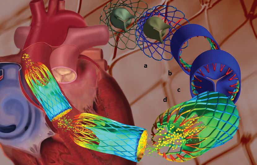
Since this cannot be accurately measured in an implanted stent, manufacturers decided to use Multiphysics to simulate the process to better understand the method and to calculate the forces operating on the implant in order to improve the stent design and the surgical procedure, as described in this article.
cfd biomechanics ansys