Our Expertise | MARINE

MICAD, engineering aimed at the sea’s jewels

CAE technologies in the Marine Industry

Newsletter EnginSoft Year 13 n°1
By Daniele Bruno | MICAD
Courtesy of Monte Carlo Yachts
Figure 1 – SpaceClaim geometry relative to a part of the structures of a yacht 30-meter length

Abstract

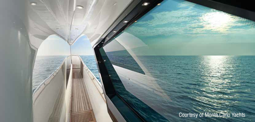
MICAD has begun his activity since 2004, the expertise in naval, mechanical and design fields of the three founders were merged to create a center of competence suitable to collect energies coming from different grounds. We are rapidly shooting up and now the team is made up of 11 people.
Our grounds are the naval and nautical fields focusing on the engineer consultancy for shipyards all over the world.
We have been working since 2010 alongside the novelty in the worldwide panorama of luxury yachting, the brand “Monte Carlo Yachts”.
They are pioneers in nautical composite materials constructions introducing for the first time the modular assembly system, for this reason they gained in 2015 the “innovation in a production process award” as a part of the prestigious new Boat Builder Awards for business achievement organized jointly by IBI magazine and METS.
MICAD is partner of Monte Carlo Yachts assisting them in their growing up.
We have also established collaborations with the giant boat builder Bénéteau, developing the naval architecture of Monte Carlo 4, Monte Carlo 6, of the last two models launched in the “Gran Turismo” gamma, the GT40 and GT46, as well as the new Swift Trawler 30.

Traditional naval architecture meets the CFD analysis with the aim to improve consolidated products reaching values in terms of performance never seen before.

Modular construction system, as well as other important innovations, is game-changer for the industry giving the possibility, for example, to cut construction time; anyway this means investments.
Naval industry has not the same capacity to invest as the automotive or aerospace ones and this means to be often a step back on the side of technical innovations.
Our goal is definitely to be the beachhead between traditions present for centuries in naval area and innovations coming from other sectors with higher quality series productions.
To transform an idea into reality is a hard task, there are a lot of small troubles that come out during the engineering process; working in close contact with real problems, we have developed a unique proficiency in helping industrial manufacturers replacing physical prototypes by virtual ones, assembling and testing products in different environments.
Virtual prototyping enables our clients to evaluate the performance of their product and the consequences of its manufacturing history, under normal or accidental conditions.
By benefiting of this information early in the process, enterprises know whether a product can be built and whether it will meet its performance and certification objectives, before any physical prototype is built.
To enable customer innovation, MICAD’s solutions integrate the latest technologies in 3D modelling and numerical analysis software for CFD as well as FEM.
With this vision we are now partner of EnginSoft.

Figure 3 - Mechanical allows to insert connections among parts defining
how parts interact with each other

Nowadays, CAE approach allows us to work close to the production having an augmented reality on numerous aspects of the product process. Innovative 3D modelling software, like SpaceClaim allows us to find instantly for example interferences or if there is enough space for the systems and equipment.
FEM and CFD work together to simulate which could be the impact of a change about any part of the project, giving advices on the stiffness of the structures for example loaded by hydrodynamic pressure.
The whole is computed fast and with a great precision, but overall software like ANSYS Mechanical, allows to have constantly a graphical view on the product in terms of 3D viewing on which users can add virtual information calculated in FEM or CFD environment.

Figure 4 - Bases of struts are fixed by displacement bounds; the aft, the fore and the bottom contour are simulated by fixed supports on their edges

For naval applications, scantling is performed through the international ISO-12215 rule (boats under 24 meters) or rules coming from the national classification societies that essentially give to the designers standard loads to assign to each structure or panel, several minimum scantling values (minimum thickness, section modulus, etc.) and criteria by which define materials.
For the case study, core of this publication, we have faced with R.I.NA, the Italian classification society for ships. Even if the modular approach of the construction process by Monte Carlo Yachts was already certified for boats under 24 meters, for the first vessel classified as “ship” of the brand (MCY 105), we had to figure out the requests of the register, checking through numerical analysis, the strength of the gluing between the fly and the deckhouse modules. The MCY 105 received “the Most Innovative Yacht Trophy - Cannes Boat Show 2015”

The biggest challenge I had was the study of the gluing among structures cause of the difficulties to model the non-linearity behavior of the adhesive.
In the image 1 is showed the case study relative to the gluing of a fly deck with the underlying structures of deck house for a yacht of 30-meter length.
The goal was to understand the behavior of the adhesive among the parts in order to verify calculations from the rules adding the contribution of gluing.
The ANSYS package provides the 3D environment SpaceClaim by which we can define the geometry, splitting or joining surface patches for example. The software is also capable to find out several faults in the mathematical definition of the shape, non-manifold edges as well as inconsistent surface normal direction.
As common workflow we usually import surfaces from CATIA or Rhinoceros and we prepare the surfaces for the next FEM simulation inside SpaceClaim environment.
The first phase was modelling the geometry simplifying the shape to build a handy geometric model, in this phase is also included splitting the geometry parts in order to recognize the surfaces on which is necessary to create a lamination and the surfaces that identify closed volumes.
The latter is useful to represent solid materials like PVC used to simulate the core for sandwich structures. Image 2 shows some 3D closed volumes representing the glue volume, with 15 mm thickness, at which we refer the material characteristics of the Crestomer adhesive.
Crestomer is a material provided by the well-known Scott Bader company, its mechanical characteristics come from the software EsaComp, another software we have at our disposal.
In Mechanical it can be possible to assign to a volume the characteristics of a specific material and on his faces the relative laminations.
About laminations, the software permits to assign the layer stratification starting from a reference surface, for this case study it was considered the external surface and the order of the layers is assigned starting from that.
This step is quite important and it must be done with great attention in particular to the directions of the layers that need to be oriented to form coupled layers. It is important, for example in a quadri-axials weaving, to set four layers oriented in + or – 45°.
Next important steps of this FEM simulation are the connections definition and the bounds assignment.

Figure 5 - Only 0.2 mm deformation at the centre zone of the 15 mm glue inserted to join
the fly to the deckhouse structures

As shown in image 3, the item is a quite complex one, it is composed by numerous parts and several laminations. Mechanical allows to insert connections among parts with the aim to create the correct physical model defining how parts interact with each other; several types of connection are available: bonded, no separation, frictionless, rough and frictional.
The first two types are linear, they need only one iteration to be solved, last three types are non-linear and require multiple iterations.
To be defined, one side of a contact pair is referred as the “contact” and its mate as the “target”, Mechanical uses a color coding system to differentiate the contact and target surfaces.
For this study case we mate the gluing volume: its top face with the bottom one of the fly floor, and its bottom with the top face of the associated plating of the deckhouse’ structures.
The other contact regions are displayed in image 3.
About supports, it is important to decide how many degrees of freedom is necessary to leave to the structure, with fixed supports is possible to constraint all degrees of freedom (dx, dy, dz, rotx, roty, rotz) on vertex, edge, or surface, with displacements is possible to allow for imposed translational displacements in x, y and z.
In ANSYS environment there are a lot of linear and non-linear supports that can help operator to identify the behavior of the physical system.

In this case study on the structure, as shown in image 4, four zones were fixed. Firstly, the base of struts through their bottom faces are fixed by displacement bounds; then, the aft, the fore and the bottom contour are simulated by fixed supports on their edges.
About loads, it is possible to define several kind of loads in different parts of the structure like edges, nodes or surfaces.
Two loads conditions respectively with a vertical pressure were applied on the floor of the fly deck and the second with an acceleration applied on the entire structure. The vertical pressure case was taken into account as base to simulate the behavior of the structure under the static loads of its mass plus all the effects and people that will be taken on board.
The case in which we are added the accelerations was useful to investigate the reactions of the structure weighed down by the loads of vertical and lateral wave motions simulated through vertical and lateral accelerations.
The symmetry was taken into account to reach the complete model holding-down the number of cells for the simulation. Symmetry condition was added to the central contour edge in order to make the structure symmetrical.

Results

After the definition of the simulation, that means after the pre-processing phase, the solver could make calculations on the discretized domain in order to report the values of the interested sizes for each node. In the post-processing phase, colored maps representing the size of interest are made in order to understand what happen in the structure like deformations or inner stress.
In image 5 is shown the deformation of the 15 mm glue inserted to join the fly to the deckhouse structures. Is easy to see how could be thin the deformation with a maximum of 0.2 mm in the center zone of the fly floor. The image is only an example of how many possibilities ANSYS has in order to perform a good post-processing phase; in this case only the deformation caused by a vertical pressure was displayed.

Conclusions

Many other tips or results could be presented in these pages but there is one important thing to remember: software are tools. Behind them there is a team of engineers and technicians.
MICAD has developed a close partnership with EnginSoft to expand our collaboration activities in other grounds and in order to share our expertise in naval and nautical fields with them.
We believe this is the only way to help our clients to get over new challenges.

Figure 2 - Closed volume, representing the glue volume of 15 mm thickness

"During my professional career started at MICAD, a yachts engineering and design studio, I challenged myself working on different difficulties projects of several lengths boats. Our goal is definitely to be the beachhead between traditions in naval constructions and innovations developed by the latest technologies in 3D modelling and numerical analysis software for CFD as well as FEM"

Find out more

software

Ansys

Explore Pervasive Engineering Simulation

Ansys offers a comprehensive software suite that spans the entire range of physics, providing access to virtually any field of engineering simulation that a design process requires.

ansys

NEWSROOM

Stay connected with us: news, analysis and trends from our experts.

Newsroom  

MEDIA CENTER

Scroll through our Media Center to view all the videos, video-tutorials and recorded webinars.

Media Center  

CASE STUDY

Interview with Diego Barone, R&D Project Leader at Vin Service

Interview with Diego Barone, R&D Project Leader at Vin Service

Vin Service, founded in 1976, is a world leader in dispenser technology and the first Italian manufacturer of draft-wine dispensers. Its core business is in the dispensing equipment industry and in cooling systems for beverages.

ansys mechanics food-beverage