Abstract
Smoke, fumes and particles all have a negative impact on your working environment thereby affecting production quality and profit. The most effective method of controlling welding fumes is extraction at source. This is however not always possible and sometimes insufficient. In such cases, Nederman offers the Air Purification Tower
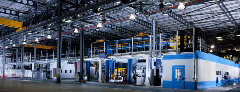
Nederman’s Air Purification Tower is the perfect choice if source extraction is not a satisfying option. Such conditions can for example be found in large workshops with changing activities and where ducting cannot be installed. The Air Purification Tower can also be a complement to existing Nederman source extraction.
Read the article