Our Expertise | MECHANICS

How to optimize an external gear pump in highly constrained conditions

Meeting the engineering challenge of increasing efficiency while reducing costs

Newsletter EnginSoft Year 14 n°1
By Manuel Rigosi | Casappa
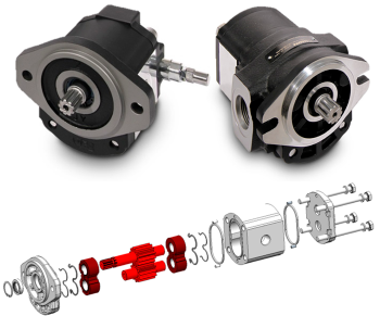
Figure 1a | Casappa POLARIS 20 external gear pump <br> Figure 1b | POLARIS 20 pump exploded view
Figure 1a | Casappa POLARIS 20 external gear pump
Figure 1b | POLARIS 20 pump exploded view

Abstract

In this technical case study, EnginSoft assists Casappa to further refine the core feature of an already optimized gear pump in order to achieve best performance in terms of efficiency and reduction of noise emission while maintaining its same level of performance. The approach adopted was to review the core feature of the pump -- the design of its gears and the interfacing lateral plates -- in order to reduce the overall noise generated by the internal oscillating forces inside the pump and by the pressure fluctuations. Since the expected performances are always higher in respect to previous versions, while complying production needs, this kind of problem becomes highly constrained.

This article details the steps and procedures followed to apply, two different ModeFRONTIER genetic algorithms: Multi-Objective Genetic Algorithm (MOGAII) versus Multi-Objective Game Theory (MOGT) to find and then test the best virtual redesign and best algorithm, in order to create a prototype for physical testing in the laboratory.

IMPROVING EFFICIENCY WHILE REDUCING NOISE IS A VERY COMPLEX ENGINEERING CHALLENGE: CASAPPA HITS THE TARGET THROUGH EXTENSIVE USE OF NUMERICAL SIMULATION

Today, any kind of hydraulic subsystem has to guarantee high performances and reliability in order to meet customer expectation while minimizing the price and time-to-market of each product. In this context, external gear pumps are simple machines that play a primary role thanks to their incomparable mix of features: extremely low-cost and simple production but with high performance and reliability at the same time. Their major limitation is their fixed displacement because variable speed electric motors are likely to become more widespread for many applications. In addition, the last few years have seen significant attention to noise reduction, especially for electrically powered systems such as indoor forklifts or hydraulic control units. The objective of this project was to take a standard series pump (PLP20, Figure 1) with a displacement of about 20 cc/rev and to minimize its noise emission, while maintaining same level of performance.

The target was not to redesign the whole pump, minimize the time-to-market of the new version, but to review its core feature, the design of its gears and lateral plates that interface with them (light and dark red highlighted components in Figure 1b). These parts are geometrically constrained by its connection to a pre-existing housing. The main purpose of the optimization was to reduce the overall noise emission of the pump: from huge internal oscillating forces inside the pump able to excite the structure (structure-borne noise) and from pressure fluctuations propagating through the hydraulic circuit (fluid-borne noise) pressure waves arise (air-borne noise) and cause annoyance in their surrounding environment. The other main purpose of optimization is the maximization of both volumetric and hydro-mechanical efficiencies (this means to reduce leakages and friction between internal components) in order to minimize power absorbed from the prime mover and consequently energy consumption of the overall system.

Figure 3 | Phase 1 - results

Figure 4 | Pump timing through lateral plates grooves

The first step of optimization was the gear design: an internally developed software was used to calculate not only standard features like gear contact ratio and tooth strength, but also more specific parameters important for a hydraulic pump, like specific displacement (quantity of oil the gear can draw for each mm of length), tooth tip, minimum tooth space volume and kinematic flow pulsation (directly related to pressure ripple and noise). This software was included inside a modeFRONTIER workflow (Figure 2) and a really fast MOGAII optimization simulated 100’000 designs in a short time: 1630 designs were feasible (better performances compared to current pump, Figure 3). The best solutions suggested an increase in the number of teeth compared to the current gear. As a further verification, the new design has been validated with KISSsoft commercial software.
Once the gear design is fixed, it is crucial to deeply analyze the meshing process (Figure 4) from a hydraulic point of view: small oil compressibility combined with trapping phase of each vane leads to huge pressure peaks and cavitation insurgence, both of them being sources of pressure ripple and noise emission. The standard solution is to machine some grooves on lateral plates in order to accurately fix the pump timing: they define when and how to connect each pumping vane to external ports. After having parametrized lateral grooves’ geometry, a precise model is necessary to properly simulate the pump’s behavior. Casappa R&D Department can count on HYGESim (HYdraulic GEar machines SIMulator, Figure 5): it is a completely customized virtual platform able to simulate gear pumps, starting from 3D CAD files. Its functioning is based on a pump lumped parameter model developed in Siemens- LMS AMESim that can simulate fluid-dynamics and basic mechanics inside the pump; also, it is coupled to other independent modules able to perform acoustic, tribological and FSI calculations. This platform has been developed through years of cooperation with University of Parma and University of Purdue.
HYGESim is composed of a hydraulic part, where each vane and all the fluid connections are described, as well as a mechanical part. It is able to predict pressure and cavitation distribution, flow/pressure ripple in the circuit, contact forces between components and as a result the volumetric and hydro-mechanical efficiencies of the pump. The optimization of pump timing was performed with modeFRONTIER workflow depicted in Figure 6. Starting from the CAD generation of lateral plate’s grooves, a C++ code combines all components’ geometries together and gives input to HYGESim circuital model, that simulates the pump in different working conditions; the resulting data is post-processed by an Octave script. 7 constraints on input variables are necessary to ensure a good interface between components; 10 constraints on output variables guarantee that the new pump will perform better than previous one in every aspect and every working condition (feasibility condition). It is a hard job for the optimizer to respect so many constraints, but at the end it properly reflects the target of this activity. 4 objective functions manage the physical quantities mostly related to noise and efficiencies.
The standard procedure (Figure 7), usually followed to solve this problem, is to define a range for each input variable, generate a good and feasible DOE population and then run the optimization with MOGAII algorithm. In case the Pareto frontier is acceptable, a further single objective optimization can be done to refine the best solution; if the frontier is not good enough, it is used to reconsider the input ranges and MOGAII settings to loop the process once more. In this specific case MOGAII results were not properly satisfying and an alternative procedure has been followed: MOGT algorithm, based on John Nash theory, was chosen because of its potentials for super-constrained problems, while adapting each setting to its requests. What follows is the report of the comparison between results obtained with both the procedures described above.

MOGAII optimization consists of 1’175 designs, for a total amount of 392 hours of computational time. Looking at the chronology of some input variables (Figure 8) there is no evidence of a proper convergence and it can also be noticed that there are only 20 feasible designs, that means 1.7% of the overall database. The bubble chart representing 4 OFs together denotes a fragmented Pareto frontier: as a consequence it would be hard to choose the best compromise solution.
MOGT algorithm requires only one design as the initial DOE population and not a big set like the previous one: in order to have a comparable analysis, one design of MOGAII DOE has been chosen as the new starting point. MOGT optimization was stopped after 194 designs, for a total amount of 65 hours of computational time. In the history charts of input variables (Figure 9) it is clear that a convergence was achieved; 74 designs are feasible, that means 38.1% of the whole set. The bubble chart shows a lower and more populous Pareto Frontier, therefore more and better designs are available in this case. To conclude, a super-constrained optimization was performed in order to find better gear and lateral plates for a new low-noise version of the Casappa PL20 pump. MOGT algorithm demonstrated itself to be 22 times more efficient than standard MOGAII in one-sixth of the time, leading to better solutions.

Figure 8 | MOGAII optimization results
Figure 9 | MOGT optimization results

Advantages and prototypes

In Table 1 the advantages obtained with the best design of each optimization are highlighted. On the basis of these promising results, the MOGT best configuration has been prototyped (Figure 10) and is going to be tested in the Lab Department.

Figure 2 | Phase 1 - gear optimization

Figure 5 | HYGESim simulation platform

Figure 6 | Phase 2 – pump timing optimization

Figure 7 | Optimization procedure

Find out more

CASE STUDY

Optimization of an automotive manufacturing system design taking into account regional requirements

Applying CAE to facilitate business CapEx decision making in the automotive manufacturing sector

In this case study, EnginSoft engineers explain how they used modeFRONTIER to assist Comau, a Fiat Chrysler subsidiary, to optimize their approach to the preliminary design of production systems for automotive manufacturing system RFQs.

automotive optimization rail-transport modefrontier SIMUL8 iphysics industry4
NEWSROOM

Stay connected with us: news, analysis and trends from our experts.

Newsroom  

MEDIA CENTER

Scroll through our Media Center to view all the videos, video-tutorials and recorded webinars.

Media Center  

CASE STUDY

New methodology to better understand fatigue life in complex components

First six months’ use demonstrates comprehensive usability for designers with open future development prospects

This technical article details the application of the methodology developed using ANSYS WorkBench

ansys mechanics maplesim