Our Expertise | AEROSPACE

Greenhouse Module for Space System

This feasibility study has been carried out to investigate and develop the characteristics of a greenhouse module for a future lunar base

Newsletter EnginSoft Year 12 n°3
By Lorenzo Bucchieri, Erik Mazzoleni | EnginSoft
Greenhouse Module for Space System
Figure 1 - Baseline design of the Greenhouse Module

Abstract

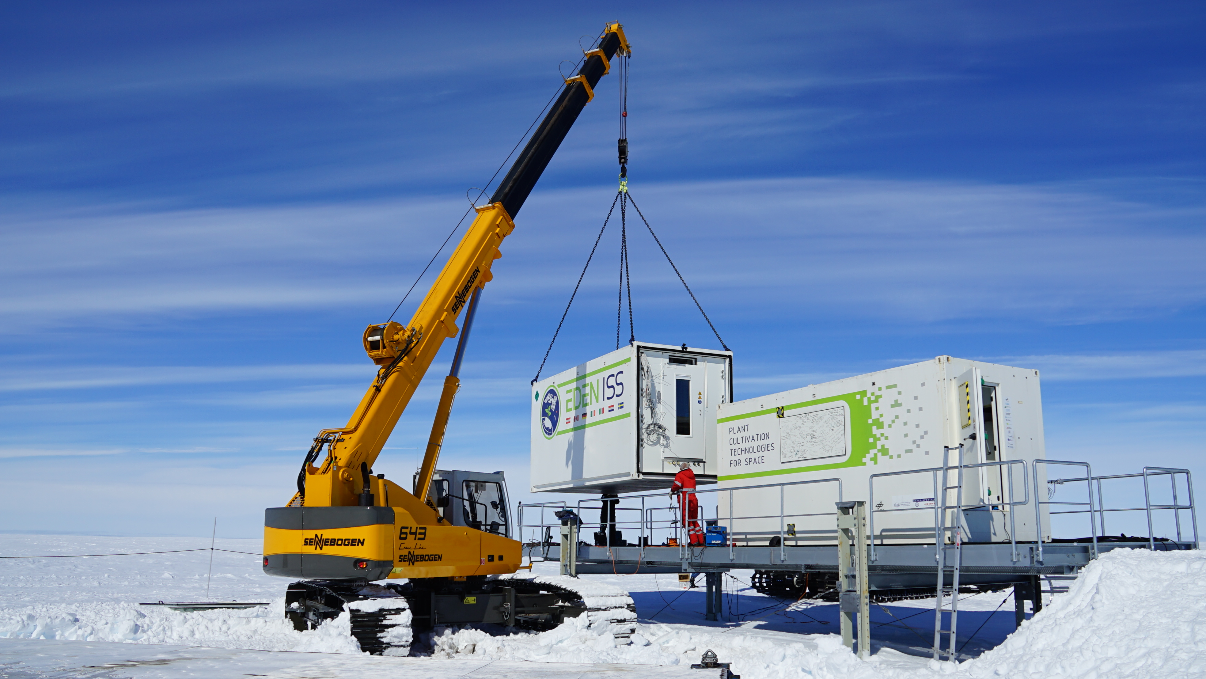
To increase the possibilities for humans to explore space, the development of bio-regenerative life support systems is essential: these systems must fulfil all human needs to sustain a sufficient living condition. In this contest, a greenhouse module is the fundamental part of every concept for a stable and independent base in future space missions. Indeed a greenhouse can (re-)generate essential resources for humans by closing different loops within a habitat, like waste water recycling, CO2 reduction, food and O2 production.
Following this aim this feasibility study has been carried out to investigate and develop the characteristics of a greenhouse module for a future lunar base. This project has been coordinated by the German Aerospace Center (DLR) and it is embedded in the MELiSSA framework of ESA research projects.

To investigate and define the technical concept of a greenhouse module on the Moon connected to an already existing habitat, different subsystems have been identified: Design/ Structure of the Greenhouse, Air Management System, Plant Health Monitoring & Quality Assurance, Nutrient Delivery System, Illumination System and Thermal/ Power Control System. Each one of these subsystem has been simultaneously developed and then combined together.

During this project EnginSoft, thanks to its experience in the field of Heat Ventilation and Air conditioning (HVAC), has worked on the Air Management System and on the interface with the habitat infrastructure. In this article we will focus on these aspects.

Baseline design of the Greenhouse Module

Looking at the global structure of the greenhouse, the design evolution during the study has led to a baseline design which is composed by a rigid core module with four inflatable petals, two connections to the lunar base structure and a solar collector to enable a hybrid natural and artificial illumination system. A sintered regolith cover around the structure was envisioned to provide micro-meteoroid and radiation protection, as well as facilitate the thermal management of the greenhouse (Figure 1).
The inner core offers space for a three-level configuration (Figure 2-Left). The lower level is the main connection point to the habitat, where two independent and pressurized corridors lead to the habitat infrastructure. The lower level of the rigid core houses the nutrient delivery system, the thermal management system, and the power subsystem with batteries for redundancy. The middle level of the central core houses the data handling and control system, and several working desks. Furthermore, the astronauts can access the petals from this level.
The lower section of the petal is reserved for storage and placement of additional subsystem components, such as inflatable tanks and pumps, as well as interface panels for resource flows (e.g. water, cooling fluid) to and from the core module (Figure 2-Right). The upper section of each petal is dedicated to plant growth and contains the plant support structure, illumination system equipment, ducts and tubing of air and thermal management system, as well as piping of nutrient delivery system.

All components are mainly placed inside the core where the air is recirculated in a loop (Figure 4-Right, Figure 5-Right). Pipping and plenum for air distribution/ collection are located inside the petal (Figure 5-Left). The connections between each petal and the air management system, located in the core, are established by two supply ducts (air form the core to the petal) and one suction duct (air from the petal to the core). With respect to the duct system two approaches have been foreseen: within the core, rigid aluminium-based duct systems are implemented, while flexible and semi-rigid ducts within the petals. The deployable ducts consist of flexible material reinforced by a wire cable built in a spiral configuration to maintain structural integrity.

To manage the air exchange between the greenhouse module and the habitants a direct gas connection is selected introducing the following operating modes (Figure 6):

  • NOMINAL MODE. Each petal has a dedicated air loop with a continuous air recirculation. Temperature, pressure and air composition is monitored and regulated. In this mode there is no air exchange with the habitat.
  • BREATHING MODE. Each petal is directly connected to the habitat infrastructure. In this mode O2-rich air can flow from the petal to the habitats and CO2-rich air can move in the opposite direction simultaneously. The breathing mode can be activated for a single petal at a time.

When nominal mode is active, the air inside the petal is completely recirculated. During the nominal mode each petal is a separate growth chamber with a dedicated air management system to control the climate. For each petal the sensor packages provide an instant feedback to the air management system in order to reach the desired temperature, pressure, humidity, and CO2 level. Due to the complete recirculation in nominal mode, the O2 level can’t be continuously regulated, but it will be maintained in a predefined range, form 21% to 26.5%. When the maximum O2 level is reached, the nominal mode is modified into the breathing mode. In the breathing mode, through a set of regulation valves that are partially or completely open, the O2-rich air can flow from the petal to the habitat and the CO2-rich air can flow in the opposite direction (from habitat to petal). During the breathing mode the O2 level inside the petal decreases till the minimum value is reached and the nominal mode can start again. For example, to increase the level of O2 from 21% to 23% (nominal mode) inside the petal (with 2.85[kg/day] of O2 plant production rate) it takes approximately 90[h] (with lights on). So the breathing mode can be activated at least every 5-6 day to decrease the level of oxygen, moving it back to 21% of O2 level. The breathing mode itself lasts only several minutes, considering no extreme recirculation effects within the petal. With a mass flow of 8200[m³/h] and a petal volume of 618[m³] the total gas exchange would be around 4-5 minutes.

CFD analyses of a growth chamber

CFD models of a growth chamber has been created to check internal climate of the petals: these simulations has allowed to calculate pressure, velocity, temperature, local concentration of O2/CO2 and humidity level.

When the nominal mode is active the air is treated in the core and then is blown down, through the supply ducts, into two plenum placed under the floor of the petal (Figure 7-Left). The air inside the (inflatable) plenum is pressurized by fans that are located just before the plenum entrance. Moreover the top surface of the plenum is perforated with circular holes (grid). The open area of the holes is the 40% of the total plenum area: this solution guarantees an uniform air distribution to the different parts of the floor. The air inside the petal is finally collected from a suction duct located at the top of the chamber.
A geometrical model of the plants has been introduced to include the principal characteristics of the plants in the CFD analysis (Figure 7-Right). Plants are represented as boxes, taking into account the maximum volume that they can occupy respect to their growth. From a fluid-dynamic point of view, an isotropic pressure resistance is applied on boxes, considering that 85% of the total volume of boxes is occupied by plants.
Plants are also sources/sinks of O2, CO2 and H2O according to the crop characteristic. In this case the cultivated crop is potato with O2 source =2.85[kg/day], CO2 sink =3.8[kg/day] and H2O source =740[l/day].

Plants are also sinks of energy: considering the quantity of evaporated water (740[l/day]) and a constant enthalpy of evaporation (2444[kJ/kg]), the total power absorbed is 35.8[W]. The heat due to lights (and other electrical equipments) is about 53[kW] and it is distributed uniformly in the part of petal volume that is illuminated by led panels.
The flow is considered in a steady condition and in a turbulent state. The energy equation is solved, but no radiation is simulated. The reference pressure is set to the atmospheric pressure. The total mass flow at the two inlets is 8200[m3/h], the temperature is 20[°C] and the inlet air composition is fixed (O2= 21%, CO2= 0.12% and RH=70%). On the outlet a relative pressure of 0[Pa] is applied. Buoyancy effects are also taken into account using the gravity of the moon.
The contour plots of the results show a velocity field in the range from 0[m/s] to 1[m/s] (Figure 8): no peak velocity values are present near plants. Higher velocity values are only present in the plenum for the supply air and around the suction duct (Figure 8). The total pressure loss between inlet and outlet is 130[Pa].
The temperature inside the chamber remains in the range from 20[°C] to 30[°C], with a temperature of 26[°C] at the outlet duct (Figure 9). The highest temperature values are present in the top part of the chamber where the heat is transported due to buoyancy effects. The change in the relative humidity is from 70% (Inlet temperature = 20[°C]) to 74% (Outlet temperature = 26[°C]). The temperature gradient remains below 10[°C], this should be compatible with the plant growth.
Other CFD calculations have been performed with the same procedure considering bread wheat as cultivated crop: some critical aspects on thermal loads and temperature gradient have been pointed out and mitigation strategies have been proposed in this case.

Conclusion

In conclusion, during this project, a greenhouse module layout has been developed, defining all the necessary subsystems for the growth of plants. Relevant issues related to bio-regenerative systems are taken into account.
In particular, the air management system has been designed with the selection and characterization of different components to control the climatic condition (velocity, temperature, air composition and relative humidity) inside each growth chamber.
A direct interface with the lunar base has been defined for O2/CO2 exchange: a switch between two operating modes (nominal and breathing mode) is able to adjust the O2/CO2 levels inside the greenhouse.
A CFD analysis has been finally performed to check the behaviour of the air management system from a fluid-dynamic point of view.

Figure 2 - Left: Core design. Right: Petal internal layout
Figure 3 - Air loop for each petal
Figure 4 - Left: mass and total power for the air management system. Right: scheme of air loop
Figure 5 - Left: air flow path inside the petal. Right: air ducts and distribution channels
Figure 6 - Left: nominal mode. Right: breathing mode
Figure 7 - Left: air flow path inside the petal. Right: CFD model of the petal
Figure 8 - Velocity distribution on two section planes
Figure 9 - Temperature distribution on two section planes

Find out more

Research project

EDEN ISS

Ground Demonstration of Plant Cultivation Technologies and Operation in Space

The aim of EDEN ISS is to identify operation procedures for safe food production in space through adaptation, integration and demonstration of higher plant cultivation techniques.

NEWSROOM

Stay connected with us: news, analysis and trends from our experts.

Newsroom  

MEDIA CENTER

Scroll through our Media Center to view all the videos, video-tutorials and recorded webinars.

Media Center  

CASE STUDY

Using high-fidelity FSI simulation and advanced mesh morphing to simulate and mitigate vortex-induced Vibrations

This study discusses the complex and challenging problem of controlling vortex-induced vibrations (VIV).

cfd mechanics ansys rbf-morph