CAE helps Aprilia Racing improve the performance of its MotoGP motorbikes
Optimising racing engine inlet ducts using fluid dynamics
Newsletter EnginSoft Year 13 n°4
By Alberto Clarich, Giulio Cassio | ESTECO
Racing engines are continuously evolved and fine-tuned to allow them to achieve extraordinary levels of performance, albeit with great complexity. However, MotoGP regulations restrict engine development by constraining some of the main design parameters. This means that traditional design methods increasingly fall short and so designers are progressively turning to new CAE methods to achieve performance improvements.
This technical paper describes a method that was used to optimize the fluid dynamics in the intake valves and ports of the Aprilia RS-GP motorbike in order to enhance the engine’s volumetric efficiency and minimize pressure losses to maximize the intake mass-flow rate – while guaranteeing design feasibility. To save time and computational processing power for the simulation, the engineers followed a two-step optimization procedure after which the new designs were validated through physical experiment.
Read the article
CASE STUDY
The America’s Cup isn’t just the first sailing competition in history, it’s also the first when it comes to innovation. Learn how American Magic engineers partnered with ESTECO to prepare for their next challenge
modefrontier marine
CASE STUDY
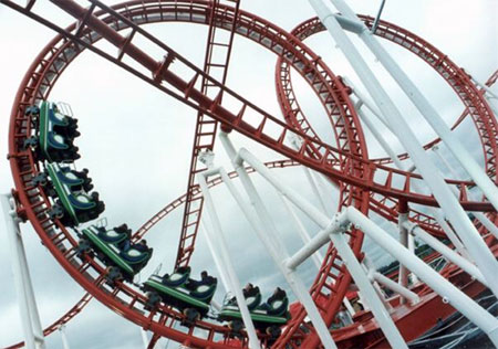
Engineers will normally need to evaluate a number of different designs, only one of which will result in the final construction configuration. This is why numerical simulation plays an indispensible role in roller coaster design.
ansys civil-engineering construction