Our Expertise | OIL & GAS

Dynamic response of a buried pipeline, under the action of the fall of rocks on the soil

Safety assessment of a buried pipeline potentially subject to rockfalls

Newsletter EnginSoft Year 13 n°3
By Massimo Tomasi | EnginSoft
<h5>Safety assessment of a buried pipeline potentially subject to rockfalls</h5>
Safety assessment of a buried pipeline potentially subject to rockfalls

Abstract

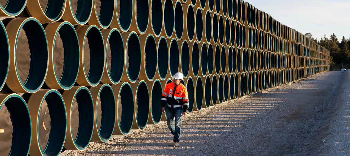
Oil or gas pipelines that cover long distances pose complex design challenges. Every environment the pipeline crosses is characterized by different potential geohazards. One of the most dangerous for a pipeline is a rockfall. This specific geological hazard, therefore, requires detailed analysis, particularly for the design of onshore pipelines. The virtual representation of the phenomenon has to be as realistic as possible; it is best approached with Finite Element Analysis which allows engineers to accurately analyse problems with high-speed, highly nonlinear dynamics. This article describes how the engineers simulated different types and impacts of rockfalls to measure their effect on different configurations of the soil and the buried pipeline below it to find the optimal burial depth and composition for the backfill soil to ensure the pipeline’s safety.

The construction of an oil pipeline or a gas pipeline over a long distance is an activity that requires a complex design. The several environments it may cross can be characterized by different geohazards to which the pipeline is subject. Among geological Hazards, rock fall is one of the most dangerous to be analyzed during onshore pipeline design. Therefore, the possibility to virtually replicate this phenomenon in a realistic way is of fundamental importance. This type of phenomena can be well simulated by means of finite elements explicit analysis, since it allows to analyze the problems of highly non-linear fast dynamics.

The aim of this activity is to investigate the dynamic response of the buried pipeline, under the action due to the fall of rocks on the soil. The objective is to evaluate the pipeline stress values considering different impact conditions: rock kinetic energy, weight and angle of impact. ANSYS WB has been adopted for model generation and AUTODYN has been used as solver. The main demand is that, in different configurations, the state of tension on the pipeline is less than the yield stress.

The investigation concerns integrity check of the pipeline, considering possible falling scenarios as a result of the geohazard risk assessment. Information related to possible scenarios of falling rocks have been provided by SAIPEM and are summarized here below:

  • Size of the boulders as a function to the temporal probability of fall.
  • Kinematic data of each boulder:
    • The position of altitude and distance from the pipeline.
    • Kinetic energy as a function of the position.
    • Height of bounce.

On the basis of such information, it has been possible to define a sensitivity study so to verify the pipeline safety conditions, in relation to the scenarios, varying the following parameters:

  • Boulder speed.
  • Angle of impact on the ground.
  • Weight of the rock.

Fig. 3 - Geometry isometric view

Fig. 4 - Geometry - Section view

Fig. 5 - Mesh

A parametric 3D CAD model has been elaborated. The model consists of a primary volume that represents the ground where the steel pipe buried is buried and backfilled and protected at the top by a concrete slab. The model is completed by a cubic boulder close to the ground surface. In Figure 3 and Figure 4 two images shown the environment that has been simulated, while Figure 5 show the mesh. In agreement with Saipem, a completely parametric model was generated, so to be able to quickly modify, the boulder size, pipeline burial depth and the backfilling soil mechanical characteristics, with the aim of identifying the most critical conditions. In addition the impact configuration is the most burdensome possible; as it can be seen from the images (Figure 3), the rock impacts on the long edge, so to investigate the worst impact conditions. In the initial phase the parameterization was used to define the length and the minimum width of the simulation environment, which is necessary not to have edge effects. In the subsequent phases, the geometrical parameterization was used to verify the improvements on the results, due to the variation of the pipeline burial depth.

The materials used to model the soil and the concrete have been obtained from ANSYS Autodyn database. For the pipeline the StE 445.7 TM has been adopted. Materials used are listed in the following table:

Tab. 1 – Materials and materials colour legend

The Figures 3 and Table 1 clearly describe how the materials have been assigned to the single components of the model. Each color refers to a single material as shown in Table1. For the fall line 7, 8 and 9 the concrete layer is not present, the material of this layer is switched into “soil landstone” as for the remaining soil around the pipeline. The rock is modeled as rigid.

Boundary Conditions

A fixed constraint is applied around and under the assembly (blue color in Figures 6); furthermore on the same faces (red color in the Figures 7), the impedance boundary condition has been applied; this setting permits to avoid the birth of reflected waves at the borders of the model; in other words the continuous waves beyond the constraint without being reflected. The contacts between each components are frictional with friction coefficient equal to 0.3.
In each analysis the Standard Earth gravity acceleration is applied and the rock has an initial velocity derived from the energy provided by the geohazard risk assesment report and a specific impact angle (Figures 8).

Fig. 6 – Fixed surfaces loads

Fig. 7– Impedance boundary

Fig. 8 - initial velocity applied to the rock

Fig. 9 - Total Deformation environment section 1

Fig. 10 - Total Deformation environment section 2

Fig. 11 - Equivalent Von Mises stress on the pipeline

Results

27 simulations were carried out; for each fall line, the total deformation of the entire assembly and the equivalent Von Mises Stress on the pipeline at the time, at which the worst condition occurs, are shown. In the following images are showed the basic output values that have been calculated.

Conclusions

In this study the behaviour of a buried pipeline under the action of indirect loads due to falling rocks was analyzed, by means of simulations with the explicit code AUTODYN. The impact conditions were taken from the geohazard risk assessment report provided by SAIPEM.
The results have shown the behaviour of the soil-pipeline system in different configurations and the related values of stress of the pipe. Such information allowed Saipem to investigate how pipeline burial depth influences the structural behaviour of the pipe subject to ground surface rock fall impacts.
Table 2 summarizes the results for each line of drop, considering the worst impact configuration, therefore more conservative one.
Downstream of these simulations, it could be taken into account the creation of response surface, using modeFRONTIER, as a function of the parameters of the rock (speed, size, angle of impact) and the soil (thickness above the pipeline), in order to assess in a fast and efficient way to other possible critical configurations.

Fig. 1 - Fall lines
Fig 2 Profile of fall - kinematic quantities boulders
Tab. 2 - Kinematic configuration, safety conditions, Added thikness soil in order to improve the safety, safety conditions after Added soil thikness

Find out more

software

Ansys

Explore Pervasive Engineering Simulation

Ansys offers a comprehensive software suite that spans the entire range of physics, providing access to virtually any field of engineering simulation that a design process requires.

ansys

NEWSROOM

Stay connected with us: news, analysis and trends from our experts.

Newsroom  

MEDIA CENTER

Scroll through our Media Center to view all the videos, video-tutorials and recorded webinars.

Media Center  

CASE STUDY

From saving energy to creating energy

Use pumps as turbines to generate low-cost electricity from existing piping systems

This article describes how SAER ELETTROPOMPE used Ansys CFX to transform "standard" pumps into pumps to be used as turbines.

energy ansys cfd