Our Expertise | AUTOMOTIVE

Development and optimization of crash brackets for ECE R29 regulation compliance

IVECO uses modeFRONTIER to simulate results to pass type-approval tests

Newsletter EnginSoft Year 17 n°4
By Esteco
Development and optimization of crash brackets for ECE R29 regulation compliance

Abstract

This paper presents the main steps taken in the development phase of the IVECO cab suspension brackets to comply with the new ECE R29 crash regulation for Heavy Commercial Vehicles (HVC). In this study, modeFRONTIER drives and guides different CAE software (Hypermesh, Radioss, Nastran and MATLAB) to fulfil all the requirements for the component under examination. The IVECO cab suspension brackets are actually designed to deform considerably during the ECE R29 tests, while still being strong enough to survive the IVECO fatigue mission without any failures.
These are two opposing goals: a typical challenge for optimization software like modeFRONTIER.

The ECE R29 requirements

Regulation ECE R29.03, which came into force in January 2011, applies to commercial vehicles with a separate, category N driver’s cabin. It prescribes the requirements for the protection of the occupants of the cabin of the vehicle in a head-on collision or in the event of overturning. This is a TYPE-APPROVAL test: you cannot sell the vehicle if it does not comply with this regulation!

ECE R29.03 comprises three different tests after each of which the cabin must exhibit a survival space that allows the accommodation of a mannequin at the 50th percentile. Further requirements are that the doors must not open during the tests, and the cabin must remain attached to the chassis.

Fig. 1 – ECE R29 regulation requirements

Test A is a frontal impact test intended to evaluate the resistance of the cabin in a head-on collision. It was already used in the previous version of ECE R29, but the kinetic energy involved has now been increased by 25%. A rectangular impactor (0.8x2.5m) with a mass greater than 1,500kg impacts the front wall of the cabin with an initial kinetic energy of 55kJ.
Test B describes an impact to the A-pillar of the cab and is intended to evaluate the resistance of the cab in the event of overturning by 90° resulting in a subsequent impact, for example against a tree, a pole, or a wall. A cylindrical impactor (0.6x2.5m) with a mass greater than 1,000kg impacts on the centerline of the windshield with an initial kinetic energy of 29.4kJ.

Test C denotes a strength test of the cab roof intended to evaluate the resistance of the cabin in the event of overturning by 180°. It is composed of two sequential sub tests:

  • A dynamic pre-test: a flat impactor, wider than the cab, and with a mass greater than 1,500kg impacts on the side of the cabin at an angle of 20° and with an initial kinetic energy of 17.9kJ.
  • A static test: the roof is crushed by a rigid plane with a minimum weight of either 10 tons or the maximum load on the front axle.

The IVECO ECE R29 simulation

IVECO performs the ECE R29.03 evaluation using virtual simulation: the FE model used is quite complex because all the details of the cab are necessary – structure, trim, suspension and so on.
This results in very long calculation times: about 24 hours using 48 CPUs which, of course, is not suitable for optimization tasks during the concept design phase.
During the evaluation of ECE R29.03 Test A, we noticed that the kinematics of the front suspension could help us to reach the goal: in detail, the blue bracket (Fig. 3) pushes back the green interface and, consequently, the red bracket. We observed that if the red bracket were to collapse we would be able to easily reach the objective.
We therefore designed a small model of the red bracket and its kinematics to study its collapse using a simulation of a few minutes: as a result, we obtained a force-displacement graph that helped us to identify the collapse and the level of force required to achieve it.

Fig. 3 – Radioss small FE model – cabin suspension bracket

The IVECO strength and durability simulation

As shown, the cabin suspension bracket should deform during the ECE R29 type-approval tests, but at the same time, it needs to be rigid and sturdy enough to survive the vehicle’s fatigue mission on the road without failure due to customer use and misuse. IVECO manages the durability test both physically and virtually; the virtual approach is time-consuming due to the tuning of the fine mesh, which has a real influence both on durability impairment and on the length of the simulation time. During the development phase, a smarter and quicker approach was used in order to reduce response time. The bracket was evaluated using:

  1. Standard static gravitational load using finite element analyses generally used for initial and preliminary dimensioning
  2. Load cases obtained from the whole load time history used for durability analyses by applying some dedicated statistical analyses

Using an envelope stress map for post-processing all the load cases enables you to detect and highlight the areas of failure in the fatigue test (see Fig. 4). On a standard workstation, execution takes a few minutes instead of a few hours using the traditional procedure for durability calculations.

FE input model for modeFRONTIER

The two FE models (Radioss and Nastran) are generated from a single Hypermesh model. Mesh morphing was used in this activity: by working on the handle nodes, it is possible to stretch, deform, and enlarge the parts thus modifying the shape and geometry of the structure. The morphing is applied simultaneously to the two different FE models and then Hypermesh exports the input file for each solver (see Fig. 5).

Output results for modeFRONTIER

The outputs from the simulations are as follows:

  • linear static simulation: Nastran writes the output data, like stress value, displacement and so on, into a text file with an f06 extension. A MATLAB script has been written to read the Nastran f06 output file and summarize all the information into a simple table that shows, for each load case, the maximum stress levels on the parts, and the number of nodes that exceed the stress limit. The extension area is used to understand if an elevated stress level is mainly due to a local peak as a consequence of deformed elements caused by the morphing tool (see Fig. 6).
  • crash analysis: Radioss creates some output text files that report the time, actuator force and actuator displacement. This information can be used to generate the graph illustrating deformation with respect to force, as shown in Fig. 7 (three different designs have been shown in the examples). We use three different points of this graph in modeFRONTIER to identify the maximum force level.

modeFRONTIER flow

The input parameters are the coordinates of the morphing nodes. A Hypermesh macro file collects all the inputs, then opens the model, morphs the parts, and writes the input files for the two software programs: Nastran and Radioss. Using the sincro node (see Fig. 8), you can run the two simulations in parallel: this reduces the total time for each design to the longer simulation time (and not to the sum of the two simulation times, as in the case of sequential execution). The simulation results are identified using the methods explained previously.

In order to achieve a better design than the original, the constraints for the Radioss crash force and the Nastran stress levels must be lower than for the initial design.
The optimization was performed in modeFRONTIER by moving the handle morphing nodes and requesting the reduction of the:

  • Maximum Von Mises stress
  • Maximum force in crash load
  • Number of nodes exceeding target stress limit

Different solution methods were used during the optimization phase, principally multi-objective genetic algorithm 2 (MOGA2), multi-objective game theory (MOGT) algorithm and fast algorithm for the scenario technique (FAST).

Fig. 8 – modeFRONTIER flow

RESULTS

The following graph in Fig. 9 shows a scatter plot reporting the:

  • Crash force to collapse the bracket (X axis)
  • Maximum Von Mises stress on the component (Y axis)
  • Number of nodes exceeding the limit (bullet diameter)

The constraint limits are indicated in the graph so that only the grey points are feasible.

At this point it is possible to identify the Pareto frontier (see Fig. 10) where some designs have been selected to see the shape and stress results obtained (see Fig. 11).
Since the original design already had an acceptable level of strength to achieve positive results in the crash type-approval testing, we decided to reduce the stress level as much as possible for more reliable durability results while maintaining the crash force level. The final design used is displayed in the following photograph (see Fig. 12) showing the component before and after the successful typeapproval test. It is possible to see that the simulation results match closely with the real deformation.
The durability test was also performed without creeks and breakage, so that the vehicle is now on the road.

A similar approach was also taken for the other suspension brackets due to the different layouts, different cabins, left/right side attachments, number of axles, vehicle typology (on-road, off-road), etc. all of which require a different bracket geometry. modeFRONTIER enabled us to automatically investigate a huge number of simulations, evaluating thousands of different shapes in just a few weeks. It is useful in the investigation and optimization of designs.

Fig. 2 – Radioss full model
Fig. 4 – Linear static analyses, envelope stress map
Fig. 5 – Morphing volume on the part to modify it
Fig. 6 – MATLAB elaboration from the .f06 Nastran file
Fig. 7 – Radioss output: force vs. displacement
Fig. 9 – Scatter plot of the results
Fig. 10 – Pareto designs
Fig. 11 – Sample design on the Pareto frontier
Fig. 12 – Final design (bracket on vehicle)

Find out more

CASE STUDY

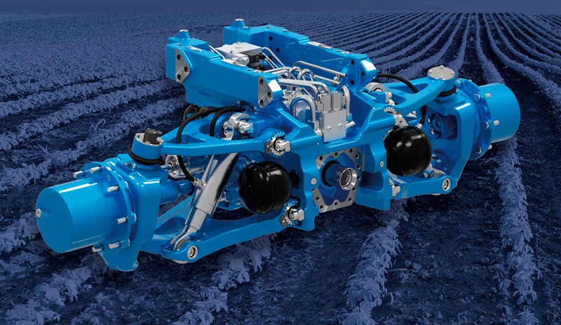
Strategy to optimize the independent suspension system of an off-highway, agricultural tractor

The purpose of the case study was to implement a design methodology that used multi-disciplinary simulation and an automated process to analyse thousands of product configurations and highlight vehicle performance distributions in terms of handling, comfort, and cost. This approach ensures that the best solution is always selected.

mechanics modefrontier automotive optimization
NEWSROOM

Stay connected with us: news, analysis and trends from our experts.

Newsroom  

MEDIA CENTER

Scroll through our Media Center to view all the videos, video-tutorials and recorded webinars.

Media Center  

CASE STUDY

High Pressure Die Casting Optimization of a Connecting Rod

A multi-objective engineering simulation study of the connecting rods manufacturing process

Connecting rods connect the pistons to the crank shaft in automotive engines and are vital components of the engine. Connecting rods are traditionally produced in ferrous metals by forging or die casting.

metal-process-simulation automotive magma