Our Expertise | AUTOMOTIVE

Cooling fan module road test simulation

For engine cooling, Johnson Electric offers smart Cooling Fan Modules (CFM) with best in class efficiency and power density

Newsletter EnginSoft Year 14 n°3
By Alberto Ballestra | Johnson Electric
Cooling fan module road test simulation

Abstract

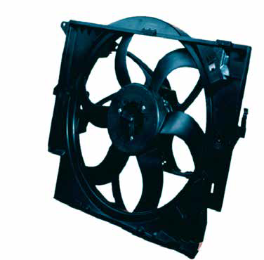
Johnson Electric is world leader in motion subsystems market. Actuators, motors, switches, solenoids, flexible circuits and CFM are some of the wide range of custom product developed projects. The industries served include Automotive, Building Automation, Home Technologies, Medical Devices, Power Tools and Lawn & Garden.
For engine cooling, Johnson Electric offers smart Cooling Fan Modules (CFM) with best in class efficiency and power density.

CFMs are composed by a brushless motor driven electro-fan with a support frame (shroud) mounted in front of the radiator. CFMs are subjected to high structural tests according to internal and customer requirements (Vibration test, Yaw test, Endurance etc.); the road test represents an important step in the product validation.

Tests are carried out in the conditions informed by the client, adopting a standard of reproducing vibration and temperature levels, and the vehicle life. The test track is composed of a mix of paved-unpaved road with portions of severe potholes, bumps and similar obstacles. This represents a challenging loading condition that is capable of creating transitory high acceleration impact, to create potential parts damage. Abrupt braking condition from 100 to 0 km/h generates an acceleration of around 0.6 G, while bumps can generate up to 6G in longitudinal direction and 10G in the vertical direction.
Structural FEAs on CFMs aim to minimize stress and displacements on new designed products, in particular to guarantee fan-radiator and fan-shroud not-touching during the whole product life. Optimization of the product starts with a strong correlation of the model with specifically designed tests under controlled conditions.

Test description, FEA implementation

A proof car is generally provided by the customer with some hours of test drives recorded in order to monitor dynamic behavior.
Accelerometers and thermocouples are mounted on the pilot CFM nodal points. In addition, an accelerometer is placed at the tip of lower frame on which the cooling box is mounted; this point represents the vibration of the body car, i.e. the vibration coming from the vehicle body can be considered as induced to the radiator/electro-ventilator by this point (Fig.1).

The most critical bump episodes are identified and introduced in an ANSYS transient analysis as input accelerations in the three space axes. Model geometry represents the CFM mounted on the radiator by means of the two lateral tanks, whose inferior part is connected to ground (lower frame of the car body) through a joint. This is used as input for the measured accelerations on the body car. A simplified model of the radiator with reduced number of plates was implemented, with equivalent dynamic properties.
Polymeric material properties are tuned by means of Experimental/FEA correlation, testing the component on a Shaker mounted in a climatic chamber (controlled temperature and humidity) and correlating natural frequencies and damping factor.
The FEA model is further calibrated on test data using damping, parts contact and joint stiffness. The measured data at rear side of the motor is compared to FEA results and used as model validation.
The correlated model gives a dynamic response in the time domain (gain, i.e. input/output acceleration ratio) similar to measures (Fig.2).

Fig.2 - FEA-test gain comparison

Geometry optimization from real data

Evaluation of stress and deformations is part of the design process. A good safety factor on fan-radiator gap along time is the aim to assure no-touch condition (fig. 3,4).
An optimization activity is carried out on the shroud. The internally developed shroud design tool can guide CAD parametric geometries and FEA analyses in the construction of a n-dimensional space of the solutions with optimization algorithms (Sobol+Full factorial). The designer can thus identify the best geometrical parameters set (component thickness, height, quantity etc.) to reduce deformations with minimum possible mass contribution (fig.6). The new reinforced shroud is virtually mounted on CFM model and FEA is relaunched for validation. This resulting gap improvement can be seen in figure 6.

Fig.6-Fan-radiator Gap ratio monitoring during bump – baseline and optimized

Conclusions

CFMs are subject to high stress in a critical environment. Road obstacles represent a challenging condition that is capable of creating transitory situations of potential damage. It is fundamental a robust structural design can be achieved to minimize stress and avoid contact between parts; at the same time the weight issue must be under control. This can be obtained with FEA optimization based on a model which were previously correlated with proper experimental data.

Fig.1 - CFM (cooling fan module) test set up, accelerometer position

Fig.3-Radiator-fan hub gap

Fig.4-Radiator-fan hub gap variation

Fig.5-Shroud design optimization tool

Fig.7- Maximum stress monitoring during bump – baseline and optimized

Find out more

software

Ansys

Explore Pervasive Engineering Simulation

Ansys offers a comprehensive software suite that spans the entire range of physics, providing access to virtually any field of engineering simulation that a design process requires.

ansys

NEWSROOM

Stay connected with us: news, analysis and trends from our experts.

Newsroom  

MEDIA CENTER

Scroll through our Media Center to view all the videos, video-tutorials and recorded webinars.

Media Center  

CASE STUDY

Ultra-Wide Band Radome CAE Optimization

Overcoming mechanical and electromagnetic challenges in refining a radome for electronic warfare

Elettronica SpA designs and produces systems for electronic warfare. Each system design is unique according to its platform and purpose. In this article, the company describes how it used CAE to approach the challenging design of a single sandwich radome.

ansys optimization electronics