Our Expertise | FOUNDRY

Comparative analysis of temperature control systems for high pressure die casting dies

Numerical methods for the thermal analysis of the HPDC process are needed to shorten the cost, the design and production time and the samples to involve in finding acceptable operating conditions.

Newsletter EnginSoft Year 13 n°1
By Paolo Callegaro, Università di Padova | Giampietro Scarpa, EnginSoft
Numerical methods for the thermal analysis of the HPDC process are needed

Abstract

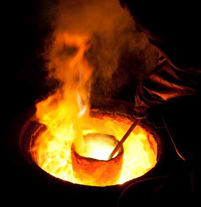
In High Pressure Die Casting production it is necessary to keep the die temperature within a certain specified range for the following basic reasons:

  • Ensure that the casting solidifies progressively from the opposite part to the running systems, in order to reduce much more as possible the porosity.
  • Reduce hot spots and make the die more isothermal.
  • Modify the grain size and microstructure to improve mechanical properties.
  • Increasing the die life time.

Working with a die at excessively low temperature there will be problems like premature solidification and incomplete filling of the die cavity, difficult ejection due to increase of shrink force and in consequence of high thermal gradients, rapid die wear, thermal shock of the die surface and also formation of cold shuts.

If the die temperature is too high there will be a fast release agent degradation and increased consumption, longer cycle time, unreliable casting dimensions and an increase of shrinkage porosities. Furthermore the soldering defect can appear, thereby resulting in low quality of the component and difficult ejection.
As a result, the correct die temperature is crucial to obtain a smooth and high level of productivity and to optimize the production cycle.
Numerical methods for the thermal analysis of the HPDC process are needed to shorten the cost, the design and production time and the samples to involve in finding acceptable operating conditions. CAE tools, like MAGMASOFT and its Optimization module MAGMAfrontier, allow to support the designer during the research of the best engineering solution.
Temperature Control Units (TCU), or Thermoregulators, are electrical mechanical devices designed to regulate dies temperature.
Thermal regulation takes place by heating or cooling a fluid, which is pushed through an electric-driven pump inside cooling channels within the die. Heat transfer is by convection between the fluid and the surface of the channels in the die and by conduction within the die steel itself.
Standard water TCUs are open tank systems which can control water temperature lower than 90°, characterized by low cost and low temperature range. Pressurized water TCUs are closed tank system which can control water temperature near to 180°C, 200 in some cases. These systems combine the possibilities to preheat the die to high temperature and to cool it efficiently with water.
Other commonly used fluids are diathermic oils, which allow to reach a maximum temperature of 350°C.
With the use of CAE software it is possible to understand the difference between the use of oil and water.

It’s important to notice that there are also localized temperature control systems like bubblers, baffles, heat pipes and Jet Cooling systems; these are useful to control specific zones of the die, the “hot spots”.
This works aims to select the best temperature control technologies for the most recurring high pressure die casting applications. In order to achieve this purpose, the die casting processes and their temperature control systems have been studied. Furthermore, process simulations with the software MAGMASOFT have been useful for the final comparison.

Simplified geometry process simulations

The first step of simulations with the software MAGMASOFT has been done on a test geometry to better understand the difference between water and oil used as fluid media. For the thermal analysis of the mold has been considered a steady state simulation.
The influence of the external environment has been denied with an insulation layer around the die and the lubrification time set at zero seconds. Thus, the thermal regime of the die depends only on the presence of the thermal regulation channels (Fig. 1).

The result of this first step is: the die temperature, using water as cooling medium at the minimum flow rate of 0.2 m3/h, is lower than the one using oil at 2 m3/h.
Moreover, the influence of the water flow rate is negligible when the values are higher than 0.8m3/h, while it’s still appreciable for oil.
The final result is that water reaches an efficiency saturation point faster than oil for its better thermal properties, as a result, the difference between the two fluids is higher when the flow rate is lower (Fig. 2).

Die temperature vs. fluid medium temperature

The thermocouple T30 was inserted in the die 15mm away from the cavity surface to monitor its temperature.
With flow rates set at maximum, 2.4 m3/h, the maximum temperature at the 20th cycle was recorded. This was repeated for flow rate set at minimum, 0.2 m3/h, for temperature from 30° C to 180° C for water, and temperature from 150° C to 300° C for oil. Fig. 3 shows the effect of fluid medium temperature in steady state temperature of the die, the arrows show the effect of the flow rate.
Oil at 0.2 m3/h has no influence in the die temperature, while water at minimum flow rate cools even faster than oil at maximum flow rate, it’s evident in the temperature zone from 150° C to 180° C (Fig. 3.)

Die temperature vs. flow rate

To better understand the effect of the flow rate, at predefined temperature for water, 30° C and 180° C, and oil, 180° C and 300° C, the maximum temperature at the 20th cycle was recorded.
The results (Fig. 4) show that the temperatures of the die decrease rapidly when flow rate increase while its value is still low. However, the decreasing rate slows down with increasing of flow rate and it results negligible for higher values. This is due to the fact that, the flow rate of the fluid medium is directly connected to the heat transfer coefficient for convection, but it rules only in the proximity of the cooling channel.

Real casting process simulations

During a real die-casting process there are many kind of boundary conditions, such as die/casting, die/air, die/cooling channel and die/lubrication. In these simulations they are considered and treated by heat-transfer coefficients across the specific interfaces.
The cycle parameters, shot curve and spray time are constant to investigate the effect of the thermoregulation but the opening time is not the same for every configurations. The difference of solidification time between water and oil is too high, thus the die opens when the virtual thermocouple T94 in Fig. 6 reach the temperature of 478°C, one degree below the solidus temperature for the aluminium alloy AlSi9Cu3 used.

The geometry used for these simulations, illustrated in Fig. 5, is part of the European Project Music and it has been shaped to create defects and to learn how to reduce them.
It’s possible to see in Fig. 5 that the difference in solidification time between the thick zones and the thin zones around is solidified to 10 seconds. This means a high probability of shrinkage porosity defects inevitable with the only use of thermoregulations. Possible solutions to the problem could be the introduction of localized temperature control systems, like jet cooling, or the adjustment of the casting geometry, or the introduction of the local squeeze to compact the alloy.
The virtual analysis highlighted that the use of water can reduce the cycle time for more than 4 seconds (Fig. 7). On the other hand, with fluid medium temperatures higher than 200°C the cycle time is longer compared to the condition without cooling channels (black line), in fact these temperatures are usually used only for preheating.
Flow rate variation brings a maximum solidification time variation of one second for water. Thus, the temperature of the fluid is much more important than its flow rate; it brings a solidification time variation of 4-5 seconds for water and 7-8 seconds for oil.

It’s, also, evident that an increasing flow rate brings to lower die temperature except when using oil at temperatures higher than 230°C. When the temperature range is from 150°C to 180°C both water and oil can be used, the difference is a much higher heat transfer coefficient for convection of water, translatable as lower temperatures of the die. Fig. 9 highlights the possibility to predict the die temperature on varying of the flow rate and the fluid medium temperature. Thus, it’s possible to choose the operating parameters to obtain the desired temperature profile within the die. A preheated die involve longer die life. Moreover, Fig. 10 shows that the steady state temperature condition is achieved faster with a preheated die; it means a potential reduction in rejected casting of 50%, even better with higher preheating temperature.

Conclusions

The ability to define the correct operating temperature of the molds can provide greater assurance of dies life while checking the quality of the castings produced.
The thermal control of the High Pressure Die Casting process is very complex and run in a single cycle time by a multitude of variables.
The work done allow to identify not only the dynamics of the cooling function of the systems used (water or oil) but also to try to give some indications of use as indicated below.
Some subjective judgments have been necessary to solve a very complex problem with a simple matrix. Actually, CAE tools like MAGMASOFT and its optimization module MAGMAfrontier, are needed to select the solution for each particular application. Nevertheless, some guidelines could reveal useful if those instruments are not available, or in order to direct the analysis on a more restricted number of alternatives.

Fig. 1 - Representation of the geometry example

Fig. 2 - Temperature of Evaluation Area 1at 20th cycle versus fluid medium flow rate

Fig. 3 - Maximum temperature of the thermocouple T30 at 20th cycle versus fluid medium temperature, flow rate from 0.2 m3/h to 2.4 m3/h

Fig. 4 - Maximum temperature of the thermocouple T30 at 20th cycle versus fluid medium flow rate

Fig. 5 - Solification time at 15th cycle

Fig. 6 - Position af the thermocouple T94

Fig. 7 - Solidification time of the casting versus fluid medium temperature (blue lines mean 0.2 m3/h, red lines mean 2.4 m3/h, black line means no cooling channels)

Fig. 8 - Position af the thermocouple T94

Fig. 9 - Maximum temperature of thermocouple T61 versus fluid medium temperature, flow rates from 0.2 m3/h to 2.4 m3/h

Fig. 10 – HeartAssist5 ® CAD model

Find out more

software

Magma

Simulation and virtual optimization of casting processes

MAGMASOFT® is the comprehensive and effective optimization tool for improving metalcasting quality, optimizing process conditions and reducing production costs.

magma metal-process-simulation

NEWSROOM

Stay connected with us: news, analysis and trends from our experts.

Newsroom  

MEDIA CENTER

Scroll through our Media Center to view all the videos, video-tutorials and recorded webinars.

Media Center  

CASE STUDY

Innovative and Integrated Technologies for the Development of Aeronautical Components

A more efficient simulation procedure for the design phase of Al-Si alloy components for the aeronautical industry.

The scope of this study was to determine and validate a more efficient simulation procedure for the design phase of Al-Si alloy components for the aeronautical industry.

aerospace magma metal process simulation