CHALLENGE
Within this article, we will demonstrate how a simplified numerical model of a calender roll can be generated and investigated using the full potential of the particle simulation software Particleworks.
Producing paper needs many process steps. A general setup of the entire paper production process can be taken from Figure 1. At the beginning of the proceeding, in the stock preparation, fiber suspension is created, screened, cleaned and refined, see [2] for further details. Subsequently, the furnish is brought onto the paper machine, in which it is dewatered. The produced paper is now rolled up at the reel section onto a metal spool to create a paper roll, which is called tambour. This is the final product of the paper machine, which can be used to perform further process steps such as calendering. Depending on the customer’s needs, calendering can take place either after the paper machine (off-line) or within the paper machine before the reel section (on-line), as shown in Figure 1.
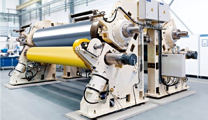
The calender can consist of several rolls to bring the required high pressure and temperature on the paper surface, see Figure 2 (left). One roll includes multiple pistons along its machine axis. The high amount of pistons is necessary to adjust the required constant pressure along the entire paper web width to ensure uniform paper surface quality. At every single piston, oil is injected so that a thin oil film is created to lubricate the rotating roll and the stationary axle, see Figure 2 (right). Additionally, the oil is used to adjust the required temperature.
SOLUTION
The calender geometry has to be simplified to a periodic numerical model. Hereto, the used numerical model takes the main components of a calender roll into account and consists of the following three parts, see Figure 3:
- Cast iron shell and plastic cover which are combined to one solid, rotating body.
- Piston (head and rod) and axle defined as two solid, stationary bodies.
- Oil volume defined as fluid body.
After pre-processing, the oil volume is numerically discretized resulting in about 700,000 particles. The oil is defined according to ISO VG 100 [4]. It is assumed that the oil temperature is constant. Particleworks version 7.0.0 is utilized as a particle-based method to perform the numerical simulations. Using the particle-based method, it was easier to realize the calender roll simulations and model all complex unsteady flow phenomena compared to “ordinary” CFD techniques, e.g. volume of fluid method (VOF). In direction of the machine axis translational periodic boundary conditions are applied. All walls are defined as adiabatic and smooth.
RESULTS
First, a simulation was performed without a piston to check, whether a stable rotating oil ring is formed or not, i.e. physical plausibility check. Hereto, Figure 4 illustrates the simulation result of the last time step, which shows a physical plausible formation of an oil ring (see left). This result is quantitatively underlined by the determined torque, which converges to a steady solution (see right). In the following, the torque is used as a target value to quantify and analyze the churning loss.
The particles of the numerical solution of the last time step are used as sample points to generate an interpolated oil surface. The interpolation result is visualized in Figure 5. Here, the impact of the partly reflected oil close to the piston head on the oil distribution can be seen.
The oil in 10 o’clock position is very turbulent compared to the flow conditions within the fluid domain. The formation of the vortices constantly requires kinetic energy to keep the vortices alive. Moreover, the turbulent oil mixing leads to energy dissipation resulting in the oil heating up. That is why generally, oil has to be removed, cooled and injected again.
The torque is determined to make a clear quantitative statement about the churning loss, see Figure 6. An oscillation of the torque can be seen which is caused by the physical phenomena described before. Since it is easier to compare integral values, first the moving average of the torque is determined. Based on this, the arithmetic mean is calculated hereafter.
Understanding the main loss generation mechanisms within a calender roll is the key to design a calender which shows a minimum churning loss. With this in mind, using Particleworks can indeed supports and accelerates the entire development process by taking full advantage in terms of virtual product testing.
By Marcus Britz | Simulation Expert, J.M. Voith SE & Co. KG | VPH
and Bettina Grashof | Senior R&D Manager Simulation, J.M. Voith SE & Co. KG | VPH
Parts of this article have been already presented and published at the VII International Conference on Particle-Based Methods PARTICLES 2021 in Hamburg (Germany) [1].
References
[1] Britz, M., Grashof, B., Wegele, P. and Linder, H.: Numerical Investigation of Churning Losses Caused by the Oil-Piston Interaction within a Calender Roll of a Paper Machine Using a Particle-Based Simulation Method. Proc. of VII International Conference on Particle-Based Methods PARTICLES 2021, Paper no. 1141, October 4-5, Hamburg, Germany (2021).
[2] Blechschmidt, J.: Taschenbuch der Papiertechnik. Carl Hanser Verlag, Ed. 2, (2013).
[3] J.M. Voith SE & Co. KG. Internal Document. (2021). [4] International Standards Organization. ISO 3448: Industrial Liquid Lubricants - ISO Viscosity Classification. Ed. 2, (1992).