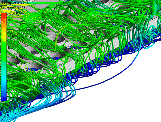
The air flow around the ACHE arrays
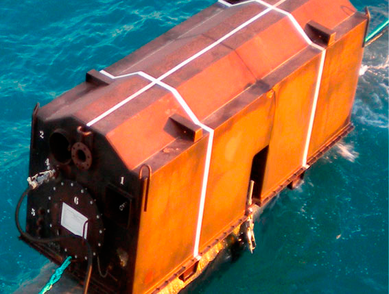
Close-up of the hot gas from the upstream turbines stacks, which does not interact with the ACHE arrays in the background
Abstract
EnginSoft developed a 3D CFD model of a Liquefied Natural Gas (LNG) Plant for the simulation of the Air-Cooled Heat Exchanger Systems’ (ACHE) arrays and their interaction with the wind.
The aim of the analysis was to predict the effectiveness of ejecting heat generated by the ACHE systems, given the plant layout and environmental conditions.
"The CFD model EnginSoft developed is able to predict the theoretical and experimental trends reported in the reference literature. We consider this to be a powerful tool that can be used to give direction to the engineering design of an optimum LNG plant layout that can mitigate the phenomenon of hot air circulation."
Process Engineer, Saipem S.p.A.