Our Expertise | RAIL & TRANSPORT

Agricultural equipment suppliers use CAE to improve product performance, safety and desirability

CAE technologies also reduce design and testing times, and design costs

Newsletter EnginSoft Year 14 n°2
By Violato Valentino, | R&D Dept. Maschio Gaspardo SpA
Improving the development of farming equipment using CAE technologies

Abstract

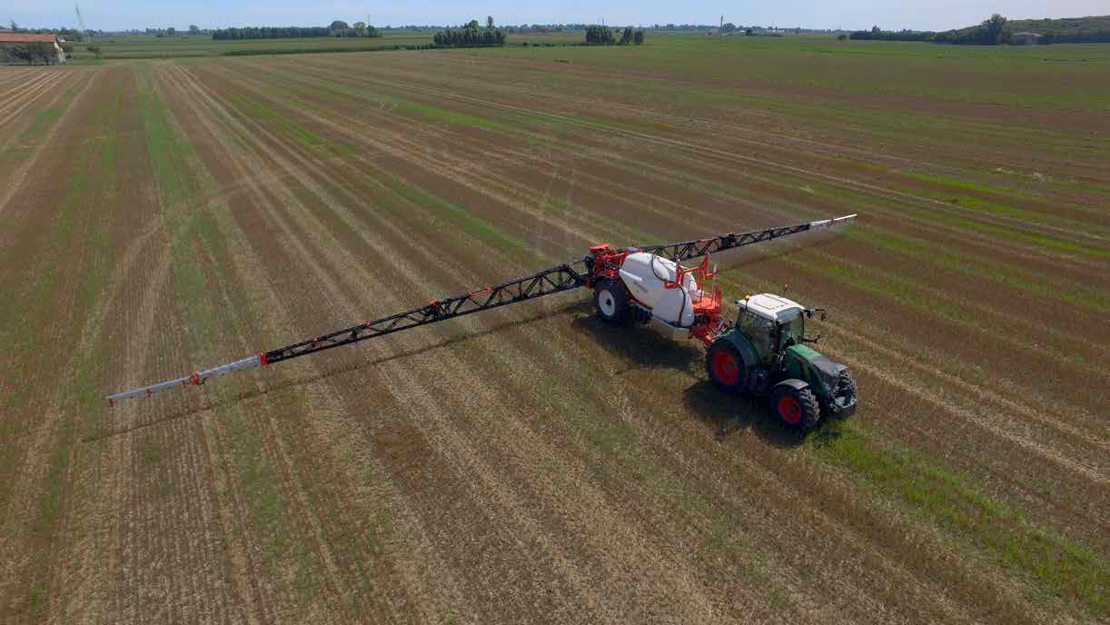
Maschio Gaspardo SpA is a leading agricultural equipment producer and supplies equipment for soil preparation, seeding, haymaking and crop protection. This case study describes how the company’s R&D team used ANYSYS and Spaceclaim to conduct Finite Element Method analyses to refine the design of a new model of a sprayer boom used by farmers to distribute phytosanitary products over fields for crop protection. The use of phytosanitary products, while important, must be limited in quantity – both to reduce costs for farmers and to reduce the negative effect of the chemicals on crop quality. The structural and dynamic performance of the spraying equipment used by farmers is fundamental to these objectives. Lightweight, reactive booms enable greater manoeuvrability, which reduces farmer work times and improves response times to threats, highly desirable factors for farmers. The case study describes the CAE techniques used in five stages of analysis on the sprayer boom’s design to reduce its weight and improve its performance and safety. The use of CAE enabled the company’s designers to reduce design costs by reducing the number of prototypes required and to shorten the design cycle.

The deep integration of ANSYS and Spaceclaim in the design process of Maschio Gaspardo SpA allows the company to evaluate the performance of its products in advance, and to improve them to ensure quality

The company

Maschio Gaspardo SpA is a leading company in the agricultural equipment market, deploying one of the widest varieties of farming implements worldwide. The production focuses on equipment for soil preparation, seeding, haymaking and crop protection.

“Crop protection” is an expression that defines all the activities aimed at defending cultivations from threats that menace (directly or indirectly) the quality and profitability of the harvest. Usually, these activities culminate in the distribution of phytosanitary products over the fields. The distribution is performed with specific implements called sprayers, mainly built following a common design: a central tank holds the mixture to be dispersed, while lateral folding beams (called spraying booms) sustain the tubing that carries the fluid over the crop. The extension of the booms allows the coverage of a wide area of work (well over 30 meters).
Although necessary to save the crop, the use of phytosanitary products has to be limited to a minimum: in fact, it represents an expense for the farmer and reduces the quality of the harvest, as a result of it having been exposed to chemicals. To ensure that the full protection of the crop is still achieved with the use of minimum quantities of phytosanitary products, the structural and dynamic performance of the spraying equipment are crucial: the stability of the booms ensures the homogeneity and accuracy of dispersion, reducing the need for over-spraying. Lightweight booms with low inertia permit the use of active control systems that continuously and efficiently modify the geometry to better follow the profile of the soil and maintain a constant spraying height. Furthermore, the reduction of weight and inertia are extremely important to enable maneuverability both on the road and on the field to permit a faster working speed. The direct benefits are the reduction of working times and the improvement of response time to threats, especially on large cultivations.

Therefore, the structural and oscillatory behavior of the spraying booms defines the ability to stand out from the competition in the sprayer market. The study and optimization of these factors therefore becomes a priority in the design process. To ensure that the new, top-of-the-line spraying boom developed by the company will meet the performance requirements defined and expected by the customers, ANSYS software has been deeply integrated into the design process, from the first design steps through to the testing and validation of the final product.

On the left, original geometry for MY16 as received from CAD. On the right, geometry after the defeaturing process

On the new spraying boom project, specific constraints imposed by the market defined the general layout of the structure as consisting of a series of sections joined with hydraulic actuator hinges. The benchmark for the study was defined using a similar model of boom from the previous year. The new boom’s performance had to match – if not improve on - this baseline, while also being significantly lighter. For the sake of simplicity, the old model is referred to as “MY15”, and the new one as “MY16”, corresponding to their years of development.
Finite Element Method (FEM) models of both MY15 and MY16 were built using similar simplifications and procedures: the aim was to obtain a significant comparative result, but at the end of the project the results also proved to be compatible with the absolute measurements.
Geometries were defeatured following standard practices and taking advantage of almost all Spaceclaim capabilities. Midsurfaces and beams were extracted, negligible features were removed and geometries were rearranged to match the configurations required for the study.
Connections, joints, local refinements and point masses were introduced in the ANSYS Mechanical model by transferring named selections and coordinate systems from Spaceclaim to ANSYS: this is a significant advantage in terms of productivity, since a rearrangement of the geometry in Spaceclaim no longer requires the user to manually adjust all the features in ANSYS Mechanical once the geometry is updated. In a similar manner, meshing is built using named selection to automate the process of region selection in case of geometry modification.

To model the weld joints of adjacent components, the “share topology” feature was widely used, ensuring a quick and computationally light representation. Another benefit of this approach is that information on the welds was not lost. In fact, local shell-to-solid submodelling remains constantly available to permit further investigation of the welded region, if required. This enables the designer to focus all the computational resources on a small portion of the frame.
Hydraulic actuators were represented either as rigid bodies or with springs and dampers elements (set up to match experimental data). The representation is chosen according to the requirements of the tests to be performed on the physical prototype at the end of the project.

An important but sometimes overlooked problem is the torsion of the boom during opening. This is a problem that lies outside the scope of the working conditions mentioned previously, but is of the utmost importance to provide the farmer with the feeling of a robust implement. A “weak” boom, that twists more than expected, would not be accepted.
The Mechanical model showed that the new MY16 boom, reinforced with local plates, manages to maintain the performance of the older model, thus satisfying the requirements of the project.

The defeaturing involved moving from tubular components to beam elements; this allowed the designers to receive information about the axial and bending loads acting on the tube, which allowed them to define safety factors against elastic instability. The tube diameters were reduced where possible and corrective actions were enforced where needed. This analysis also provided information about the loads on the various hinges, allowing the definition of contact pressure and the correct sizing of bushings.

For safety purposes, booms are required to have a so-called “safety joint” at a certain distance from the tip: if the boom hits an obstacle (such as a tree, a pole etc.) between the safety joint and the tip, the applied force/displacement will disengage the joint. Regulations require the boom to sustain the hit and remain undamaged when travelling below a certain speed. To compare the safety coefficients of the worst-case scenario hit, static analyses were set up for both MY15 and MY16: static structural analyses would beconsidered suitable if they were below the speed defined by regulations.
The analyses once again assessed the quality of the MY16 design, which showed safety coefficients in the same range or above those of MY15. As an additional result, the analysis provided the designer with a first indication of the boom’s bending stiffness against actions moving in the same direction as the boom’s forward motion.
In moving from Stage 1 to Stage 2 of the study, the features that had been set up in Spaceclaim and ANSYS to automatically adjust and rebuild the models really came in handy and required only a small number of inputs from the user to adapt the model to the new configuration.

Spraying booms hold spraying nozzles, which are all required to have the same ground clearance along the boom. On a perfectly flat field, this produces a constant spraying pattern beneath the implement. Ifthere are large vertical displacements along the boom’s path, however, the spraying pattern becomes irregular. The performance of active control systems is also hindered, since the actual position of the nozzles is different to the position they are assumed to be at by their software. One may think that simply adjusting the height of the nozzles to counteract the effects of the deformed land shape would work, but this is not sufficient: while the adjusted position would be correct in stationary conditions, during field use, a high value of stiffness is required to avoid noticeable deformations when the sprayer travels over uneven tracks.
Therefore, stiffness in the vertical direction must be evaluated. This was carried out at this stage.

The Mechanical model predicts a vertical stiffness for MY16 close to that of MY15, which satisfies the imposed requirements: spraying nozzles are held at an almost horizontal line over the sprayer’s 36-meterwidth.

Example of torsional analysis performed

Analyses performed to this point aimed to define the boom’s behavior in static situations: stiffness and mass interacted, but an overall view of the relationship between them was lacking. To address this, modal analyses were performed on the MY15 and MY16 booms. Modal analyses sum up the results of interest in a convenient way, providing designers with “comparable” indices (natural frequencies and mode shapes) while also informing the team of designers about possible resonance problems.
A frequent problem with the comparison of modal results on complex structures lies in the inability to recognize the same mode shape on different geometries. This process becomes extremely tricky when modes that are clearly distinct on one geometry tend to become mixed on another. In our case, MY15 and MY16 were different products that shared many core features in the base structure: this led to them having similar mode shapes which made it easier to compare the output.

The results were promising: moving from MY15 to MY16, every mode shape was shifted to higher frequencies. In considering the frequencies of common excitations acting on the system, it could be stated that this shift had a positive effect on the boom’s behavior: the appearance of detrimental mode shapes would be reduced, resulting in a more stable boom. A significant exception was one related to the torsional mode: its appearance (mode “h”) was expected to lower frequencies, but this was not considered as a problem since the torsional mode is hardly subjected to any excitation during field use.

Up to this point, the static and modal results were extremely useful for comparing MY15 and MY16, but their behavior in a real, dynamic scenario was still unknown. To evaluate this situation, a braking simulation was performed. This condition was chosen because it is the most demanding, from a structural point of view, during field operation. It is also extremely useful for evaluating the quality of the spraying action: the backward and forward motion created in the booms during braking is one of the major causes of over-spraying of the crop; a situation that must be avoided by reducing the amplitude of the movement and its duration.

The simulation was run by assigning an initial velocity to the structure, after which a deceleration was imposed on the joints that connected the booms to the sprayer’s main frame, based on experimental data.
Once again, the MY16 proved to have an efficient design. The deceleration input excited only the first mode shape in the horizontal plane (this was similar to the deformed configuration observed in Stage 2), and MY16, which exhibits much less inertia than MY15, reduced the overshoot by about 20% compared to that of the old model (the overshoot was defined by picking the sprayer’s main frame as a reference).

Overshoot of an older model of spraying boom during the braking action

Overshoot of a boom in the transient analysis.
Different colors correspond to different positions on the boom, picked to evaluate how different nozzles are affected by the braking action

Conclusions

The boom’s new design was thoroughly evaluated during the project, using static, modal and transient analyses. Maschio Gaspardo SpA’s FEM team and its design team interacted profitably to address the weaknesses that emerged and to further reduce the weight and increase the safety coefficients of the product. The final design, once transferred to a physical prototype, behaved according to the analyses (thus validating the numerical work) and satisfied the project requirements: the new boom is lighter than the old model and exhibits significant improvements in stability. The substantial use of FEM analyses reduced the need for additional prototypes and reduced the development time compared to old projects. During the creation and refinement of this product, which was performed according to Maschio Gaspardo SpA’s new R&D guidelines,, Ansys acquired such importance that it has become an irreplaceable tool in the design process. Its conjoined use with Spaceclaim further augmented its capabilities, allowing for fast transfer of geometry, defeaturing and analysis, even with complex and large assemblies.

Example of mesh obtained on the defeatured geometry prior to the simulation of the whole assembly
Effect of low torsional stiffness on older boom models
Bending effect on the vertical plane. On top, ideal condition. Below, actual configuration
Mode shapes and associated frequencies: comparison between MY15 and MY16

Find out more

software

Ansys

Explore Pervasive Engineering Simulation

Ansys offers a comprehensive software suite that spans the entire range of physics, providing access to virtually any field of engineering simulation that a design process requires.

ansys

NEWSROOM

Stay connected with us: news, analysis and trends from our experts.

Newsroom  

MEDIA CENTER

Scroll through our Media Center to view all the videos, video-tutorials and recorded webinars.

Media Center  

CASE STUDY

Using CAE simulation to verify the structural safety and performance of a two-wheeler’s driving mechanism

Coupled simulation methods enables more accurate evaluation

In this article, we describe how Piaggio used computer-assisted engineering simulation to evaluate the structural safety, performance and dynamic behavior of the driving mechanism of a two-wheeled vehicle under both normal and spurious operating conditions, specifically static and fast dynamic conditions.

automotive multibody