Our Expertise | AUTOMOTIVE

A new methodology based on LS-DYNA for integrating product & process engineering of a steel wheel

Wheels are products with key geometrical and structural specifications.

Newsletter EnginSoft Year 7 n°1
By Federico Valente - ITACAe Srl | Davide Fabio Rovarino - MW Italia
<p>A new methodology based on LS-DYNA for integrating product & process engineering of a steel wheel</p>

A new methodology based on LS-DYNA for integrating product & process engineering of a steel wheel

<p>Images of the wheel and its two components from a CAD model</p>

Images of the wheel and its two components from a CAD model

Abstract

Wheels are products with key geometrical and structural specifications. The wheel must fulfil load, fatigue and weight requirements, as well as geometry, stiffness and environmental resistance. In addition, new style requirements are coming from the OEM’s. To satisfy these demands the wheel manufacturer must have a deep insight into new materials and manufacturing processes as well as a robust design methodology to correctly consider both process and product constraints.
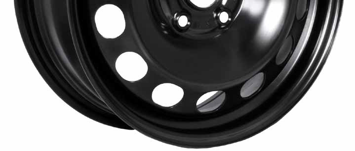
Steel wheels for passenger cars and commercial vehicles usually consist of two parts: rim and disc. The rim is the part that is in contact with the tire: international norms regulate most of its geometrical characteristics to guarantee functionality of pieces developed by different wheel and tire manufacturers.
The disc is the part that provides the connection between the vehicle’s suspension (hub) and the rim. Except for its central part, which is imposed by the customer, the disc profile is less standardized than the rim since it needs to be designed by taking into account several variable interfaces (brake callipers, trims, …) and performance requirements (fatigue resistance, bolt hole resistance, …) which are specific for each project.

The first part of the article describes the whole manufacturing process as well as the currently used prototype and virtual testing techniques. Afterwards, a new methodology is presented, following an integrated process-product analysis approach, showing some benefits related to increased accuracy and the potential application of new optimization methods.

Fig. 2 - 2D drawing scheme of the disc forming operations from a steel blank

The disc begins as a flat blank sheet of opportune size, but the process of deformation to reach the final shape consists of several stamping operations (usually nine steps at maximum). Each disc is designed to satisfy specific customer’s requirements, strongly influencing its geometry. Taking into account the main characteristics of wheel discs, you can consider the stamping process as a sequence of progressive deforming phases covering drawing, forming, flanging, cutting and coining operations.

Rim forming process

From a steel coil a rectangular blank sheet is cut: the width and thickness of the blank are characteristics of the whole coil, whilst cutting operations are set depending on the calculated length to obtain the desired rim size. The starting blank sheet is curved to create a cylindrical shape, the edges are welded and the final welded surface is refined and recalibrated to ensure the “roundness” of the piece. In order to obtain the desired rim profile, the previous cylindrical piece is deformed through four progressive rolling operations (flaring and usually three roll forming steps) and then calibrated. A specific zone of the rim is locally deformed to create an opportune flat area; the valve hole is cut (centered on the flat surface) and coined to avoid burrs all around.

Fig. 3 - Scheme of the rim forming operations from a steel cylinder

Wheel Mounting and Painting

When disc and rim are available, the wheel manufacturing process ends with the mounting phase, when the disc is pushed into the rim creating a forced fitting joint (in most cases, the disc flange and the rim well are in contact); then the two components are additionally linked thanks to usually four welding seams.

Standard FE Stress Analyses

Thanks to its internal know-how and CAD/FEM simulation tools, MW can design wheels which satisfy the customer requirements in terms of fatigue resistance, dynamic behavior, overall dimensions and so on. During the optimization phase the purpose is to find a compromise product balancing the achievement of the best performance with the lowest weight and cost. During the product design phase, FE analyses are performed to verify the fatigue resistance of different solutions taking into account the customer fatigue specifications related to the project in study. FE models represent the fatigue tests made on specific rigs for the homologation of wheels: Rotating Bending Moment and Dynamic Rim Rolling. Discs and rims are usually modelled by plate elements with constant thickness, set at the nominal value. Fatigue loads are approximately simulated as static distributions of nodal forces; linear calculations are performed and the consequent stress levels generated on the wheel are related to standard acceptable values coming from correlation with historical laboratory test results.

Fig. 4 - Scheme of the disc-rim force-fitting operation

Rotating Bending Moment

Rotating Bending Moment is one of the tests applied to assess the fatigue behavior of wheels and is particularly focused on evaluating the fatigue resistance of the disc. The test machine has a driven rotating device whereby either the wheel rotates under the influence of a stationary bending moment or the wheel is stationary and is subjected to a rotating bending moment. The rim of the wheel without the tyre is securely clamped to the machine bench. The wheel is mounted on the hub and tightened using the procedure as specified by the vehicle or the wheel manufacturer. To apply a bending moment to the wheel, a force is applied parallel to the plane of the mounting surface of the wheel at a specified distance (moment displacement vector).

Fig. 5 - Scheme of the Rotating Bending Moment machine

We are far from achieving a comprehensive integrated product-process FE based analysis methodology, due to the complexity of the range of physical phenomena to be modelled. Figure 6 describes some of the most relevant operations in the manufacturing process and their effects on fatigue behavior. The effects of some operations are experimentally known, but they are not quantified. The presented simulation approach represents a first step forward in the direction of the methodology definition, considering some of the most relevant phases in the manufacturing process. The approach is based on performing the three major steps entirely within LS-DYNA:

  • Simulation of the whole disc forming process.
  • Simulation of the disc-rim fitting-force operation.
  • Simulation of the rotating bending moment fatigue test on the wheel, after application of stress-strain distributions obtained from the previous steps.
  • LS-DYNA has been chosen, after an intensive benchmark campaign, due to the following key aspects:
  • Explicit solver Best in Class;
  • Robust and Reliable Implicit solver;
  • Fully coupled Implicit and Explicit solver;
  • Automatic results mapping;
  • Accurate springback prediction;
  • Improved Wizard in LS-PrePost 4.1 dedicated to the stamping analysis set-up;
  • Availability of complementary tools: Dynaform, VPG, etc.
  • Effectiveness of Italian LS-DYNA distributor (EnginSoft SpA) support;
  • Fast and really scalable.

Fig. 6 - Some effects of the manufacturing process on fatigue (circled the ones analyzed in this article)

Some aspects of the methodologies are outlined here below:
Simulation of all the forming process operations (4 forming + 1 trimming) with explicit algorithm
*CONTROL_ADAPTIVE used, with 4 levels and a starting mesh size=30 mm, to reduce CPU time
Analysis of springback, force-fitting, bolt tightening and bending moment with implicit algorithm
*CONTACT_TIED_NODES_TO_SURFACE used to connect disc-rim welding seam surfaces
New mesh of the disc built from the mesh of the disc after springback calculation
*INCLUDE_STAMPED_PART used to rezone thickness strain and plastic strain distributions from the mesh of the disc after springback to the mesh built for the following steps

Fig. 7 - The simulation procedure, from the initial steel blank to the wheel stress analysis

Final stresses used as parameters to perform a compared analysis among results obtained with different configurations, i.e. fitting the disc with variable values of rim internal diameters (different disc-rim interference), or deep drawing with variable values of process parameters (friction coefficient, blankholder forces) & material properties (s-e curve) within their own ranges.

Summary of results

The simulation procedure can show the degree to which particular operations affect the final stress distribution on the wheel disc and therefore the fatigue behavior of the wheel submitted to a testing load:

  • The distribution of stresses in the disc outer and inner surfaces, in particular at the profile wall and peak areas are significantly affected by the disc forming process, and in particular the thickness strain distribution;
  • Stresses are induced especially in the vent hole area by the force fitting operation, proportional to the disc-rim interference value, but are much lower compared to the stresses due to the bench test and can be neglected.

Future opportunities

The use of an integrated simulation procedure with LS-DYNA opens new opportunities to perform a more robust design of a wheel starting from a good knowledge of all design and manufacturing constraints and the ownership of the most suitable simulation techniques. Some of possible future steps are identified as follows:

  • Complete a sensitivity analysis by varying material and forming process parameters within their actual ranges;
  • Based on the results of the previous step, define a methodology, based on analyses of the force-fitting operation and the bench test;
  • Apply a similar procedure to the analyses of all the other manufacturing processes;
  • Define & experimentally validate a methodology comprising all of the most significant manufacturing processes.

Fig. 8 - Stress distribution on the wheel after bending moment, considering the disc forming& the force-fitting processes, on inner surface (left) and outer surface (right); increments with respect to results obtained without considering the manufacturing process are indicated

Fig. 9 - Stress distributions on the wheel after bending moment, considering disc forming & force-fitting with low (left) and high (right) interference: no significant differences are detected

Find out more

software

Ansys LS-DYNA

One of the most flexible finite element analysis software packages

Ansys LS-DYNA is a general-purpose finite element program capable of simulating complex real world problem

ls-dyna

NEWSROOM

Stay connected with us: news, analysis and trends from our experts.

Newsroom  

MEDIA CENTER

Scroll through our Media Center to view all the videos, video-tutorials and recorded webinars.

Media Center  

CASE STUDY

Numerical simulations for the structural performance assessments: a connecting rod’s case study

Piaggio Group uses CAE to ensure a new product design’s safety and durability

The connecting rod is one of the most important components in powertrain systems, so it requires very careful structural analyses because its failure implies serious damage to the entire engine.

automotive ansys rail-transport